
STM32N657X0H3Q Nucleo Development Board Debug Log
This board is ridiculous — TrustZone, FSBL, OTP… why is everything so complicated?
1. Debugging Journey
First Attempt: SRAM Mode
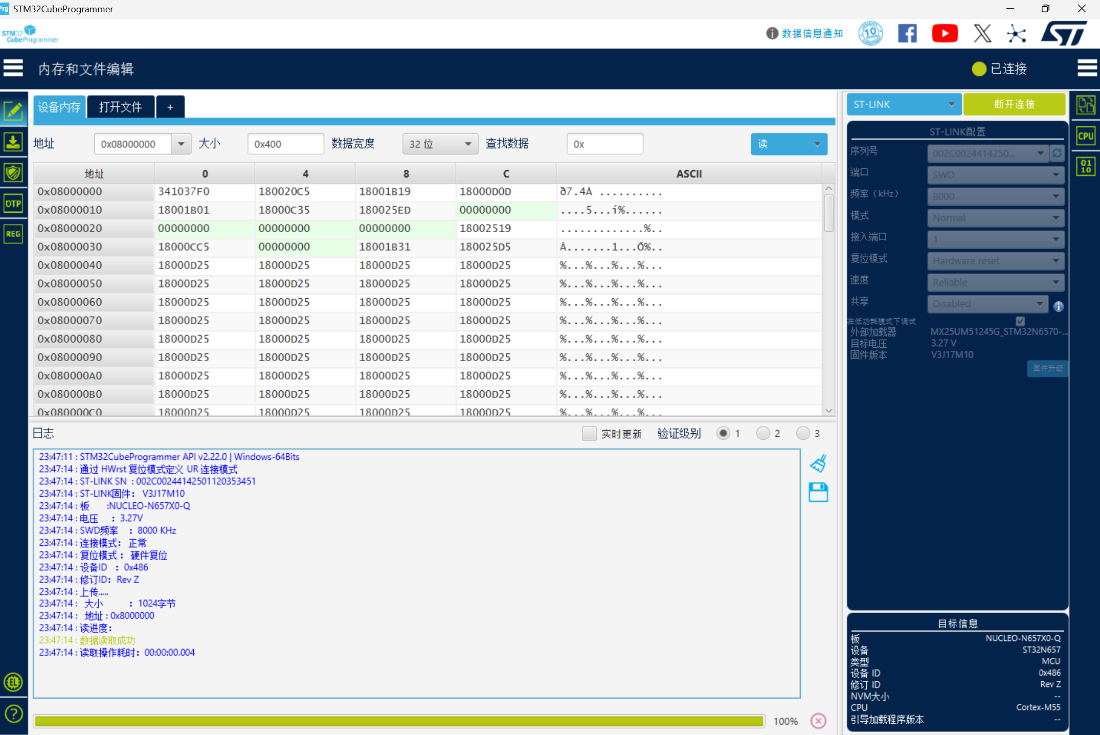
Following the familiar F1 and F4 workflow, I configured the project in CubeMX and loaded it into VS Code for debugging. Surprisingly, debugging actually worked.
But it wouldn’t run standalone — after a Reset, the code just disappeared. Looking back, this was because I was using SRAM mode: the code was loaded directly into SRAM for debugging. The benefit was being able to see results and debug in real-time, but the problem was that the code wasn’t actually being stored anywhere. Storing code requires writing it to Flash, which means configuring the XSPI interface.
Pitfall: The NUCLEO-N657X0-Q has no internal Flash. Code must be stored in external XSPI Flash. When debugging in SRAM mode, power loss means code loss — this explains why the code “disappeared” after Reset.
XSPI + XIP Mode Attempt
XIP stands for Execute In Place — the program runs directly from external Nor Flash without copying to SRAM. XSPI (eXtended SPI) is ST’s serial peripheral interface protocol for communicating with external Flash. The configuration process is quite involved.
I attempted the XSPI approach but got nowhere. Problems kept piling up — flashing and debugging both threw errors. The official forum post was configured for the DK board, and I’m not sure if there are differences between DK and the NUCLEO board, so I gave up.
Pitfall: XIP mode configuration is extremely complex, requiring:
- Memory-Mapped Mode configuration so the CPU can access external Flash via bus
- External Flash .stldr loader file (STM32CubeProgrammer needs the correct External Loader)
- Correct linker script (
STM32N657XX_ROMxspi*.ld)-alignparameter when signingThe DK board (Development Kit) and NUCLEO board may have different configurations. Official tutorials target the DK board, so many settings don’t apply to NUCLEO.
LRUN Mode: Success
LRUN (Load and Run) uses FSBL + Application working together. FSBL initializes the system and copies the Application code to SRAM. My understanding: the PC pointer is transferred to Application just before entering the infinite loop. So the infinite loop never executes. I placed the LED blink before the infinite loop, before entering Application.
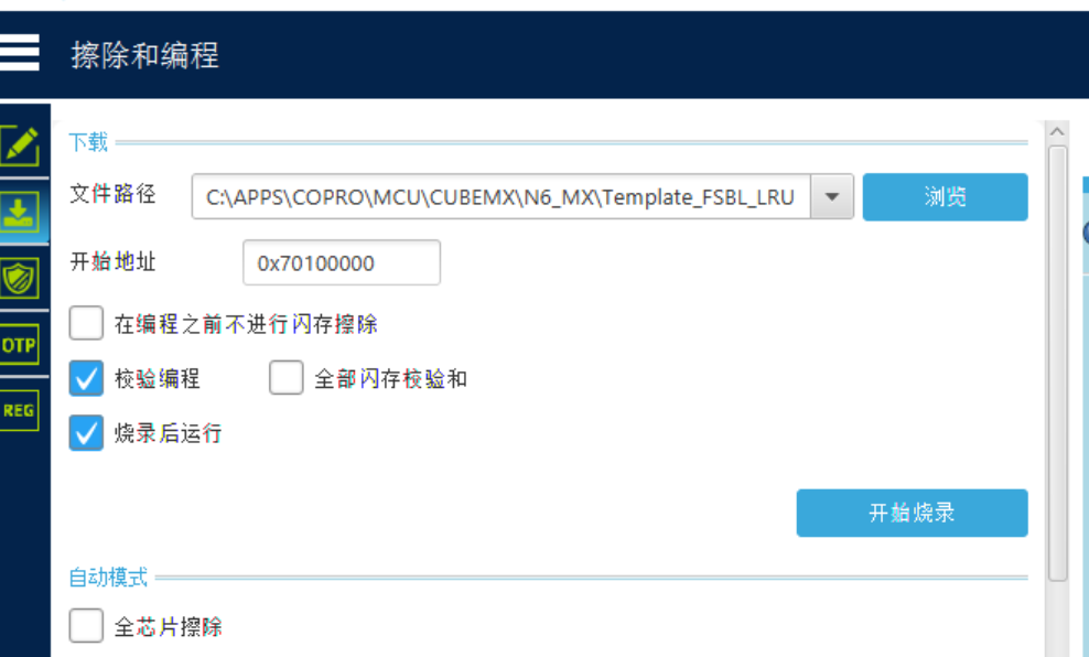
Then things went smoothly — compile and flash. After compilation, sign the binaries, then flash each one separately. Theoretically you should flash FSBL first, then Application. But in practice, the onboard program should already be in LRUN mode, so flashing either one works fine. It’s just a matter of FSBL pointers — Application is its own program, no real difference.
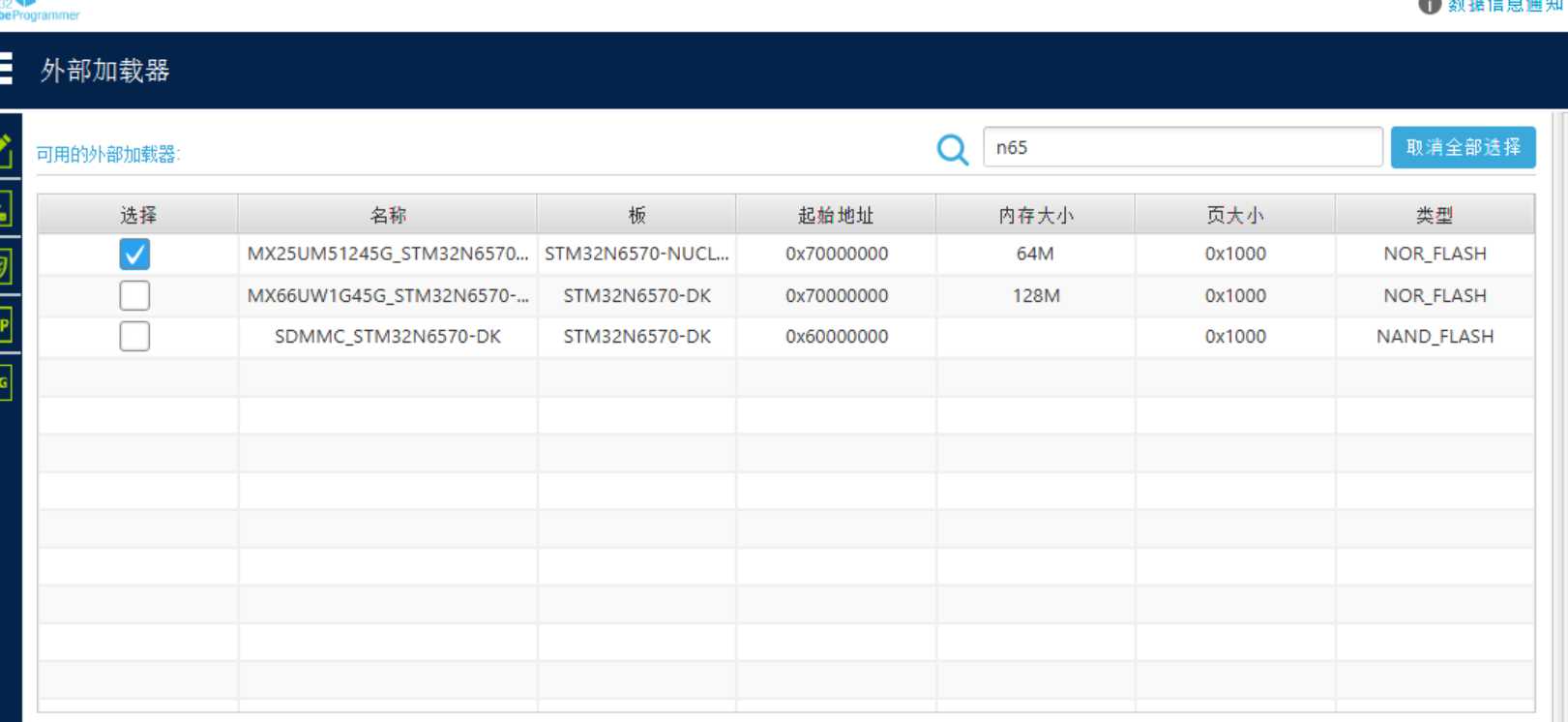
One important note: when flashing, you need to select the external memory settings — that .stldr file. Select the one matching this board, then proceed. When flashing, I got a “Core locked” popup. Previously it showed “Write Protection PROTECTION” — not sure why.
Pitfall: “Core locked” or “Write Protection PROTECTION” during flashing is usually an Option Bytes issue. Try:
- Hold Reset while flashing
- Use Mass Erase to erase the entire chip
- Check BOOT jumpers are correctly set (DEV mode: BOOT1 = 2-3)
Also, you need to load the correct External Loader (.stldr file) in CubeProgrammer before flashing, otherwise external Flash won’t be recognized.
2. Hardware Platform & Key Concepts
2.1 Chip & Development Board
- Chip: STM32N657X0H3QU
- Board: NUCLEO-N657X0-Q (MB1940)
- Architecture: ARM Cortex-M55 with Helium (MVE) + TrustZone
- Clock: 600 MHz
- Flash: No internal Flash, relies on external XSPI Nor Flash
- RAM: 2MB AXISRAM (0x3400_0000 ~ 0x3420_0000)
STM32N6 differs from F1/F4 series in several key ways:
- No internal Flash: Code must be stored in external XSPI Flash
- TrustZone: Secure and Non-Secure worlds are isolated, requiring proper RIF configuration
- Dual-domain architecture: Secure and Non-Secure domains are separate
- OTP Fuses: One-time programmable fuses for high-speed mode configuration
- FSBL mechanism: First Stage Boot Loader
2.2 LED Pins
| Color | Pin | Note |
|---|---|---|
| Green LED | PG.00 (LED_GREEN) | Appli main loop control |
| Blue LED | PG.08 (LED_BLUE) | Appli main loop control |
| Red LED | PG.10 (LED_RED) | FSBL debug indicator |
Correction: Previous notes listed PG.08 as yellow, but it’s actually blue (LED_BLUE). The silkscreen on NUCLEO-N657X0-Q matches the BSP definition.
2.3 Boot Mode (Boot Pin)
The board has 3 Boot pin positions (headers 1, 2, 3), selected via jumpers:
Boot Pin Configuration
| Pin | Headers 1-2 Short | Headers 2-3 Short |
|---|---|---|
| BOOT0 | 0 (Low) | 1 (High) |
| BOOT1 | 0 (Low) | 1 (High) |
Boot Modes
| Mode | BOOT0 | BOOT1 | Description |
|---|---|---|---|
| DEV (Debug) | Any (0 or 1) | 1 (Headers 2-3) | IDE loads program to RAM, source-level debugging |
| Boot from Flash | 0 (Headers 1-2) | 0 (Headers 1-2) | Boot from external XSPI Flash, standalone |
| Reserved | 1 | 0 | Reserved |
| System ROM | 0 | 0 | Built-in chip ROM (rarely used) |
Note: In DEV mode, BOOT0 can be anything, only BOOT1 = 1 is required (jumper on 2-3).
2.4 Boot ROM Startup Sequence
After power-on, the STM32N6 Boot ROM searches for bootable code in this order:
| Order | Address | Description |
|---|---|---|
| 1 | 0x7000 0000 | Primary: External XSPI Flash (FSBL or headered program) |
| 2 | Internal ROM | Factory-installed BootLoader (if any) |
| 3 | RAM | If nothing else found, try booting from RAM |
Note: Address
0x7000 0000is the mirror start address of external Flash. Physical Flash is accessed via XSPI interface. Only signed programs at this address are recognized by Boot ROM.
2.5 Glossary
| Abbr. | Full Name | Meaning |
|---|---|---|
| LRUN | Load & Run | Code copied from external Flash to internal RAM for execution |
| XIP | eXecute In Place | Code executes directly from external Flash, no RAM copy |
| XSPI | eXtended SPI | ST’s serial peripheral interface protocol for external Flash communication |
| FSBL | First Stage Boot Loader | First-stage bootloader |
| OTP | One-Time Programmable | One-time programmable fuses |
2.6 Linker Script Naming Convention
Format: ROM_location_RUN_RAM_location
| Linker Script | Meaning |
|---|---|
STM32N657XX_LRUN | Appli in internal RAM (loaded by FSBL) |
STM32N657XX_ROMxspi1 | Appli in external XSPI1 Flash, execute in place |
STM32N657XX_ROMxspi2 | Appli in external XSPI2 Flash, execute in place |
STM32N657XX_LRUN_RAMxspi2 | Appli in RAM, loaded from XSPI2 Flash |
STM32N657XX_ROMxspi1_RAMxspi3 | Appli in XSPI1, RAM in XSPI3 |
3. FSBL Load & Run Mode
3.1 Architecture Overview
FSBL LRUN mode divides the system into two independent subprojects:
| Subproject | Responsibility | Execution Location |
|---|---|---|
| FSBL | Initialize OTP, configure XSPI2, read/copy Appli, jump | Internal RAM (0x3400_0000) |
| Appli | User application, controls LEDs and peripherals | Internal RAM (0x3400_0400) |
3.2 FSBL Code Analysis
FSBL core code in FSBL/Src/main.c:
int main(void)
{
    SCB_EnableICache();
    SCB_EnableDCache();
    HAL_Init();
    SystemClock_Config();  // Configure 600MHz system clock

    // OTP configuration (required on first flash)
#ifndef NO_OTP_FUSE
    if(OTP_Config() != 0){
        Error_Handler();
    }
#endif

    MX_GPIO_Init(); // Initialize LED (PG.10)
    MX_XSPI2_Init(); // Initialize XSPI2 interface
    MX_EXTMEM_Init();
    BOOT_Application();   // Copy Appli to RAM and jump

    while (1) { __NOP(); }  // Never reaches here
}
FSBL execution flow:
- Enable caches: ICache + DCache
- Configure clock: 600MHz
- OTP configuration: Set VDDIO3_HSLV fuse (only needed on first flash)
- Initialize GPIO: Configure LED pin PG.10 (debug)
- Initialize XSPI2: Communicate with external Flash
- Initialize external memory:
MX_EXTMEM_Init() - Jump to execution:
BOOT_Application()copies Appli to RAM and jumps
3.3 OTP Configuration Details
OTP_Config() configures VDDIO3_HSLV fuse bits:
#define BSEC_HW_CONFIG_ID    124U
#define BSEC_HWS_HSLV_VDDIO3 (1U<<15)  // VDDIO3 high-speed mode enable
⚠️ Warning: OTP fuses are one-time write, irreversible. Confirm before configuring. Disable
NO_OTP_FUSEmacro on first flash.
3.4 Appli Code Analysis
Appli code in Appli/Src/main.c:
int main(void)
{
    SystemCoreClockUpdate();
    MPU_Config();
    SCB_EnableICache();
    SCB_EnableDCache();
    HAL_Init();
    BSP_LED_Init(LED_GREEN);
    SystemIsolation_Config();  // Configure RIF resource isolation
    MX_GPIO_Init();

    while (1)
    {
        HAL_GPIO_TogglePin(GPIOG, GPIO_PIN_0);  // Green LED
        HAL_GPIO_TogglePin(GPIOG, GPIO_PIN_8);  // Blue LED
        HAL_Delay(750);
    }
}
SystemIsolation_Config() configures TrustZone resource isolation:
static void SystemIsolation_Config(void)
{
    __HAL_RCC_RIFSC_CLK_ENABLE();
    HAL_GPIO_ConfigPinAttributes(GPIOG, GPIO_PIN_0, GPIO_PIN_SEC|GPIO_PIN_NPRIV);
    HAL_GPIO_ConfigPinAttributes(GPIOG, GPIO_PIN_8, GPIO_PIN_SEC|GPIO_PIN_NPRIV);
    HAL_GPIO_ConfigPinAttributes(GPIOG, GPIO_PIN_10, GPIO_PIN_SEC|GPIO_PIN_NPRIV);
}
3.5 Skip FSBL and Run Appli Directly
You can skip FSBL and flash Appli directly if any of these conditions are met:
- OTP already configured (VDDIO3_HSLV set)
- Chip has built-in FSBL at
0x7000 0000 - Boot ROM supports direct loading from
0x7010 0000
Steps:
- Sign Appli:
Appli-trusted.bin - Flash to
0x7010 0000 - Reset, chip boots from external Flash
Pitfall: If the chip has no built-in FSBL and Boot ROM doesn’t support direct loading, skipping FSBL will cause the chip to not find executable code and hang.
4. Build Configuration
4.1 Toolchain
| Tool | Path |
|---|---|
| GCC ARM Compiler | C:\Users\Q\AppData\Local\stm32cube\bundles\gnu-tools-for-stm32\14.3.1+st.2 |
| STM32Cube Firmware | C:\Users\Q\STM32Cube\Repository\STM32Cube_FW_N6_V1.3.0\ |
| Signing Tool | C:\APPS\Programmer\bin\STM32_SigningTool_CLI.exe |
4.2 Build Commands
cd build/Debug
cube-cmake --build . --target clean
cube-cmake --build . --target all
4.3 CMake POST_BUILD Configuration (Auto-Signing)
find_program(OBJCOPY arm-none-eabi-objcopy PATHS
    C:/Users/Q/AppData/Local/stm32cube/bundles/gnu-tools-for-stm32/14.3.1+st.2/bin
    NO_DEFAULT_PATH
)

add_custom_command(TARGET ${CMAKE_PROJECT_NAME} POST_BUILD
    COMMAND ${OBJCOPY} -O binary $<TARGET_FILE:${CMAKE_PROJECT_NAME}>
            ${CMAKE_BINARY_DIR}/${CMAKE_PROJECT_NAME}.bin
    COMMENT "Generating binary"
)

add_custom_command(TARGET ${CMAKE_PROJECT_NAME} POST_BUILD
    COMMAND ${OBJCOPY} -O ihex $<TARGET_FILE:${CMAKE_PROJECT_NAME}>
            ${CMAKE_BINARY_DIR}/${CMAKE_PROJECT_NAME}.hex
    COMMENT "Generating HEX"
)

# Auto-signing (runs automatically after build, no manual signing needed)
find_program(SIGNING_TOOL C:/APPS/Programmer/bin/STM32_SigningTool_CLI.exe)
add_custom_command(TARGET ${CMAKE_PROJECT_NAME} POST_BUILD
    COMMAND ${SIGNING_TOOL} -bin ${CMAKE_BINARY_DIR}/${CMAKE_PROJECT_NAME}.bin
            -nk -of 0x80000000 -t fsbl
            -o ${CMAKE_BINARY_DIR}/${CMAKE_PROJECT_NAME}-trusted.bin
            -hv 2.3 -align -s
    COMMENT "Signing ${CMAKE_PROJECT_NAME}.bin"
)
4.4 NO_OTP_FUSE Macro Configuration
FSBL build macros in FSBL/mx-generated.cmake:
set(MX_Defines_Syms
    USE_HAL_DRIVER
    STM32N657xx
    NO_OTP_FUSE # Comment this out to enable OTP configuration
)| Configuration | Description |
|---|---|
Disable NO_OTP_FUSE | Required on first flash, FSBL will auto-configure OTP fuses |
Enable NO_OTP_FUSE | For development, skip OTP configuration |
4.5 Build Outputs
| File | Location |
|---|---|
| FSBL.elf / .bin / .hex | FSBL/build/Template_FSBL_LRUN_FSBL.* |
| Appli.elf / .bin / .hex | Appli/build/Template_FSBL_LRUN_Appli.* |
| FSBL-trusted.bin | FSBL/build/Template_FSBL_LRUN_FSBL-trusted.bin |
| Appli-trusted.bin | Appli/build/Template_FSBL_LRUN_Appli-trusted.bin |
5. Signing & Flashing
5.1 Why Signing is Required
STM32N6’s external Flash stores critical firmware. The chip’s Boot ROM only loads images with correctly signed Headers. The signing tool adds a V2.3 format header to the .bin file.
5.2 Manual Signing Commands
# Appli signing
& "C:\APPS\Programmer\bin\STM32_SigningTool_CLI.exe" `
    -bin "C:\APPS\COPRO\MCU\CUBEMX\N6_MX\Template_FSBL_LRUN\Appli\build\Template_FSBL_LRUN_Appli.bin" `
    -nk -of 0x80000000 -t fsbl `
    -o "C:\APPS\COPRO\MCU\CUBEMX\N6_MX\Template_FSBL_LRUN\Appli\build\Template_FSBL_LRUN_Appli-trusted.bin" `
    -hv 2.3 -align -s

# FSBL signing
& "C:\APPS\Programmer\bin\STM32_SigningTool_CLI.exe" `
    -bin "C:\APPS\COPRO\MCU\CUBEMX\N6_MX\Template_FSBL_LRUN\FSBL\build\Template_FSBL_LRUN_FSBL.bin" `
    -nk -of 0x80000000 -t fsbl `
    -o "C:\APPS\COPRO\MCU\CUBEMX\N6_MX\Template_FSBL_LRUN\FSBL\build\Template_FSBL_LRUN_FSBL-trusted.bin" `
    -hv 2.3 -align -s
5.3 Signing Parameter Reference
| Parameter | Description |
|---|---|
-bin | Input .bin file path |
-nk | No Key, development mode, no actual signature verification |
-of 0x80000000 | Option flags address offset |
-t fsbl | Binary type: FSBL type |
-hv 2.3 | Header version (N6 requires 2.3) |
-align | Required, payload aligned to 0x400 |
-s | Silent mode, no overwrite confirmation popup |
5.4 Flash Addresses
| File | Address |
|---|---|
Appli-trusted.bin | 0x7010_0000 |
FSBL-trusted.bin | 0x7000_0000 (optional) |
5.5 Post-Flash Behavior
| Stage | Behavior |
|---|---|
| FSBL initialization | Red LED (PG.10) blinks 3 times |
| Jump to Appli | Green (PG.00) and Blue (PG.08) LEDs blink alternately |
5.6 External Loader (.stldr)
When flashing external XSPI Flash, CubeProgrammer needs the corresponding External Loader file:
| Board | Loader File |
|---|---|
| NUCLEO-N657X0-Q | NUCLEO_N657X0_Q.stldr (usually in CubeProgrammer installation directory) |
Location: Usually at C:\Program Files\STMicroelectronics\STM32Cube\STM32CubeProgrammer\ExternalLoader\.
Pitfall: Without loading the correct .stldr file, CubeProgrammer cannot recognize external Flash, causing errors or failure to write during flashing.
6. Debugging Methods
6.1 DEV Mode Debugging (Recommended)
- Set BOOT1 = 2-3 (DEV mode)
- IDE loads
FSBL/build/Template_FSBL_LRUN_FSBL.elfto RAM - Set breakpoints in Appli code
- Debug/Run
- FSBL runs → loads Appli → breakpoints hit
6.2 Flash Mode
No source-level debugging possible. Rely on LED / UART / ITM.
7. Project File Structure
Template_FSBL_LRUN/
├── CLAUDE.md              # Project documentation
├── SKILL.md              # Skill documentation
├── README.md              # Official documentation
├── Template_FSBL_LRUN.ioc # CubeMX configuration
│
├── FSBL/                  # FSBL subproject
│   ├── Src/
│   │   ├── main.c         # FSBL main program
│   │   ├── extmem.c       # External memory initialization
│   ├── Inc/
│   │   ├── main.h
│   │   └── extmem.h
│   ├── mx-generated.cmake # Build macros
│   ├── CMakeLists.txt
│   └── STM32N657XX_LRUN.ld
│
├── Appli/                 # Appli subproject
│   ├── Src/
│   │   ├── main.c # Appli main program
│   ├── Inc/
│   │   ├── main.h
│   │   └── stm32n6xx_nucleo_conf.h
│   ├── mx-generated.cmake
│   ├── CMakeLists.txt
│   └── STM32N657XX_LRUN.ld
│
├── Drivers/               # HAL drivers (in-project)
├── Secure_nsclib/          # Secure/non-secure call library
├── gcc-arm-none-eabi.cmake # Toolchain configuration
└── mx-generated.cmake       # Main CMake configuration
8. References
ST Official Community Posts
- How to create an STM32N6 FSBL Load and Run
- Nucleo-N657X0-Q unable to upload code
- Debugging program in external flash XIP mode STM32N6
- How to debug STM32N6 using STM32CubeIDE
- How to execute code from external serial NOR
- How to build an AI application from scratch on the Nucleo-N657X0
- STM32N6570-DK LRUN project does not boot
- How to build an AI application from scratch on the STM32N6570-DK
ST Official PDFs
- rm0486 — STM32N657xx ARM-based 32-bit MCUs
- um3234 — How to proceed with Boot ROM on STM32N6 MCUs
- an6265 — Getting started with STM32N6 MCUs in STM32CubeIDE
- an5967 — Getting started with hardware development for STM32N6 MCUs
- um3249 — Getting started with STM32CubeN6 for STM32N6 series
- pm0273 — STM32 Cortex-M55 MCUs Programming Manual
- Nucleo-N657X0-Q Schematic (en.mb1940-n657x0q-c02-schematic)
- um3417 — STM32N6 Nucleo144 board MB1940
9. Quick Troubleshooting Guide
| Symptom | Possible Cause | Solution |
|---|---|---|
| Flash error “Core locked” | Option Bytes locked | Hold Reset while flashing, or Mass Erase |
| Flash error “Write protection” | Read protection RDP enabled | Use Mass Erase |
| Flash mode not running | Missing -align in signature | Re-sign with -align |
| Flash mode not running | OTP not configured | On first flash, disable NO_OTP_FUSE so FSBL configures OTP |
| Chip unresponsive | Debugger disconnected | Press Reset, reconnect |
| Breakpoints not hitting in debug | Using Flash mode | Switch to DEV mode, BOOT1=2-3 |
| No .bin file after build | CMakeLists.txt missing post-build | Add objcopy commands |
| Signing “binary not found” | PowerShell quoting issue | Use & "..." or run in CMD |